
Product Description
1111111111111111111111111111111111111111111111111111111111111111111111111111111111111111111111111111111111111111111111111111
| Item No. | φD | L | L1 | W | M | Tighten the strength(N.m) |
| SG7-11-30- | 30 | 50 | 18.5 | 13 | M3(4) | 1.2 |
| SG7-11-40- | 40 | 66 | 25 | 16 | M4(6) | 2.7 |
| SG7-11-55- | 55 | 78 | 30 | 18 | M5(4) | 6 |
| SG7-11-65- | 65 | 90 | 35 | 20 | M5(6) | 6 |
| SG7-11-80- | 80 | 114 | 45 | 24 | M6(8) | 10 |
| SG7-11-95- | 95 | 126 | 50 | 26 | M8(4) | 35 |
| SG7-11-105- | 105 | 140 | 56 | 28 | M8(4) | 35 |
111111111111111111111111111111111111111111111111111111111111111111111111111111111111111111111111111111111111111111111111111111111111111111111111111111111111111111111111111111111111111111111111111111111111111111111111
| Item No. | Rated torque | Maximum Torque | Max Speed | Inertia Moment | N.m rad | Tilting Tolerance | End-play | Weight:(g) |
| SG7-11-30- | 7.4N.m | 14.8N.m | 20000prm | 8.7×10⁻⁴kg.m² | 510N.m/rad | 1.0c | +0.6mm | 50 |
| SG7-11-40- | 9.5N.m | 19N.m | 15000prm | 1.12×10⁻³kg.m² | 550N.m/rad | 1.0c | +0.8mm | 120 |
| SG7-11-55- | 34N.m | 68N.m | 13000prm | 4.5×10⁻³kg.m² | 1510N.m/rad | 1.0c | +0.8mm | 280 |
| SG7-11-65- | 95N.m | 190N.m | 10500prm | 9.1×10⁻³kg.m² | 2800N.m/rad | 1.0c | +0.8mm | 450 |
| SG7-11-80- | 135N.m | 270N.m | 8600prm | 1.9×10⁻²kg.m² | 3600N.m/rad | 1.0c | +1.0mm | 960 |
| SG7-11-95- | 230N.m | 460N.m | 7500prm | 2.2×10⁻²kg.m² | 4700N.m/rad | 1.0c | +1.0mm | 2310 |
| SG7-11-105- | 380N.m | 760N.m | 6000prm | 3.3×10⁻²kg.m² | 5800N.m/rad | 1.0c | +1.0mm | 3090 |
Best Practices for Installing a Motor Coupling for Optimal Performance
Proper installation of a motor coupling is essential to ensure optimal performance and reliability of the power transmission system. Follow these best practices when installing a motor coupling:
1. Correctly Match Coupling Type:
Select a motor coupling type that is suitable for the specific application and operating conditions. Consider factors like torque requirements, misalignment tolerance, and environmental factors when choosing the coupling.
2. Ensure Proper Alignment:
Achieve precise alignment between the motor and driven equipment shafts before installing the coupling. Misalignment can lead to premature wear and reduced efficiency.
3. Check Shaft Endplay:
Verify that the shafts have the correct endplay to allow for thermal expansion and contraction. Inadequate endplay can lead to binding or increased stress on the coupling and connected components.
4. Clean Shaft Surfaces:
Ensure that the shaft surfaces are clean and free of any debris or contaminants before installing the coupling. Clean surfaces promote proper coupling engagement and reduce the risk of slippage.
5. Use Correct Coupling Fasteners:
Use the specified fasteners, such as bolts or set screws, provided by the coupling manufacturer. Tighten the fasteners to the recommended torque values to secure the coupling properly.
6. Verify Keyway Alignment:
If the coupling has a keyway, ensure that it aligns correctly with the key on the motor and driven equipment shafts. Proper keyway alignment prevents rotational slippage and ensures efficient torque transmission.
7. Lubrication:
If the coupling requires lubrication, apply the appropriate lubricant as recommended by the manufacturer. Proper lubrication reduces friction and wear on coupling components.
8. Perform Trial Run:
Before putting the system into full operation, perform a trial run to check for any abnormalities or vibrations. Monitor coupling performance and check for leaks, noises, or other signs of issues.
9. Regular Inspection and Maintenance:
Conduct regular inspections and maintenance on the motor coupling and the entire power transmission system. Check for wear, alignment, and any signs of damage, and address any issues promptly.
10. Follow Manufacturer Guidelines:
Always follow the manufacturer’s installation guidelines and recommendations for the specific coupling model. Manufacturer guidelines provide essential information for optimal performance and safe operation.
By adhering to these best practices, you can ensure that the motor coupling functions efficiently and contributes to the overall performance and reliability of the mechanical system.
“`
Temperature and Speed Limits for Different Motor Coupling Types
Motor couplings come in various types, and each type has its temperature and speed limits. These limits are essential considerations to ensure the coupling operates safely and efficiently. Here are the general temperature and speed limits for different motor coupling types:
1. Elastomeric Couplings:
Elastomeric couplings, such as jaw couplings and spider couplings, are commonly used in a wide range of applications. They typically have temperature limits of approximately -40°C to 100°C (-40°F to 212°F). The speed limits for elastomeric couplings typically range from 3,000 to 6,000 RPM, depending on the specific coupling design and size.
2. Gear Couplings:
Gear couplings are known for their high torque capacity and durability. The temperature limits for gear couplings are usually between -50°C to 150°C (-58°F to 302°F). The speed limits for gear couplings can be as high as 5,000 to 10,000 RPM or more, depending on the size and design.
3. Disc Couplings:
Disc couplings provide high torsional stiffness and are often used in precision applications. The temperature limits for disc couplings are typically around -40°C to 200°C (-40°F to 392°F). The speed limits for disc couplings can range from 5,000 to 20,000 RPM or more.
4. Grid Couplings:
Grid couplings are known for their shock absorption capabilities. The temperature limits for grid couplings are usually between -30°C to 100°C (-22°F to 212°F). The speed limits for grid couplings typically range from 3,600 to 5,000 RPM.
5. Oldham Couplings:
Oldham couplings are often used to transmit motion between shafts with significant misalignment. The temperature limits for Oldham couplings are generally around -30°C to 80°C (-22°F to 176°F). The speed limits for Oldham couplings are usually up to 3,000 to 5,000 RPM.
6. Diaphragm Couplings:
Diaphragm couplings are suitable for applications requiring high precision and torque transmission. The temperature limits for diaphragm couplings are typically between -50°C to 300°C (-58°F to 572°F). The speed limits for diaphragm couplings can be as high as 10,000 to 30,000 RPM.
It is essential to check the manufacturer’s specifications and recommendations for the specific coupling model to ensure the coupling operates within its intended temperature and speed limits. Operating the coupling beyond these limits may lead to premature wear, reduced performance, or even catastrophic failure. Properly selecting a coupling that matches the application’s temperature and speed requirements is critical for reliable and safe operation.
“`
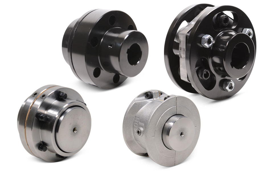
Types of Motor Couplings and Their Applications in Different Industries
Motor couplings come in various types, each designed to meet specific requirements and applications in different industries. Here are some common types of motor couplings and their typical uses:
1. Rigid Couplings:
Rigid couplings provide a solid and inflexible connection between the motor shaft and the driven equipment. They are ideal for applications where precise alignment and torque transmission are critical. Rigid couplings are commonly used in machine tools, robotics, and high-precision industrial equipment.
2. Flexible Couplings:
Flexible couplings are designed to accommodate misalignment between the motor and driven equipment shafts. They can handle angular, parallel, and axial misalignment, reducing stress on bearings and increasing the system’s flexibility. Flexible couplings find applications in pumps, compressors, conveyors, and other machinery where misalignment may occur due to vibration or thermal expansion.
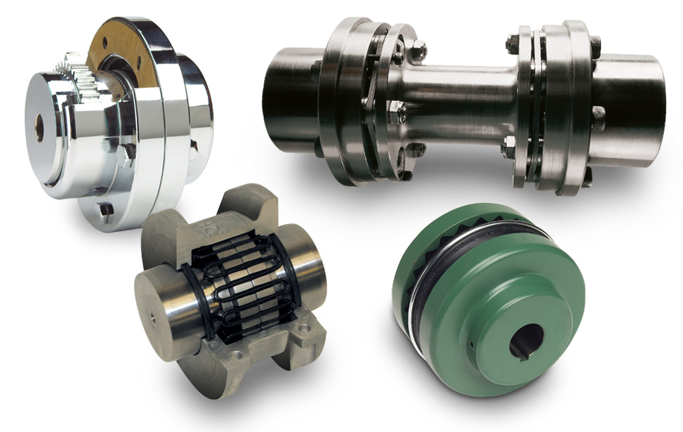
3. Gear Couplings:
Gear couplings use toothed gears to transmit torque between the motor and the driven equipment. They provide high torque capacity and are suitable for heavy-duty applications, such as steel rolling mills, cranes, and marine propulsion systems.
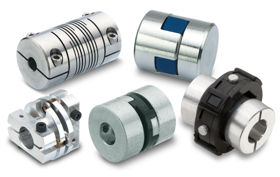
4. Disc Couplings:
Disc couplings use thin metal discs to transmit torque. They offer high torsional stiffness, allowing precise motion control in applications like servo systems, CNC machines, and robotics.
5. Jaw Couplings:
Jaw couplings use elastomeric elements to dampen vibrations and accommodate misalignment. They are commonly used in small electric motors and general-purpose machinery.
6. Bellows Couplings:
Bellows couplings have a flexible accordion-like structure that compensates for misalignment while maintaining torsional rigidity. They are used in vacuum systems, optical equipment, and other high-precision applications.
7. Grid Couplings:
Grid couplings use a flexible grid element to transmit torque and dampen vibrations. They are suitable for applications in pumps, compressors, and conveyor systems where shock loads and misalignment are common.
8. Magnetic Couplings:
Magnetic couplings use magnetic fields to transmit torque between the motor and driven equipment. They are commonly used in applications requiring hermetic sealing, such as pumps and mixers handling hazardous or corrosive fluids.
Each type of motor coupling offers unique advantages and is chosen based on the specific needs of the industry and the application. Proper selection and installation of the right coupling type enhance efficiency, reliability, and safety in motor-driven systems across various industries.
“`

editor by CX 2023-11-27