
Product Description
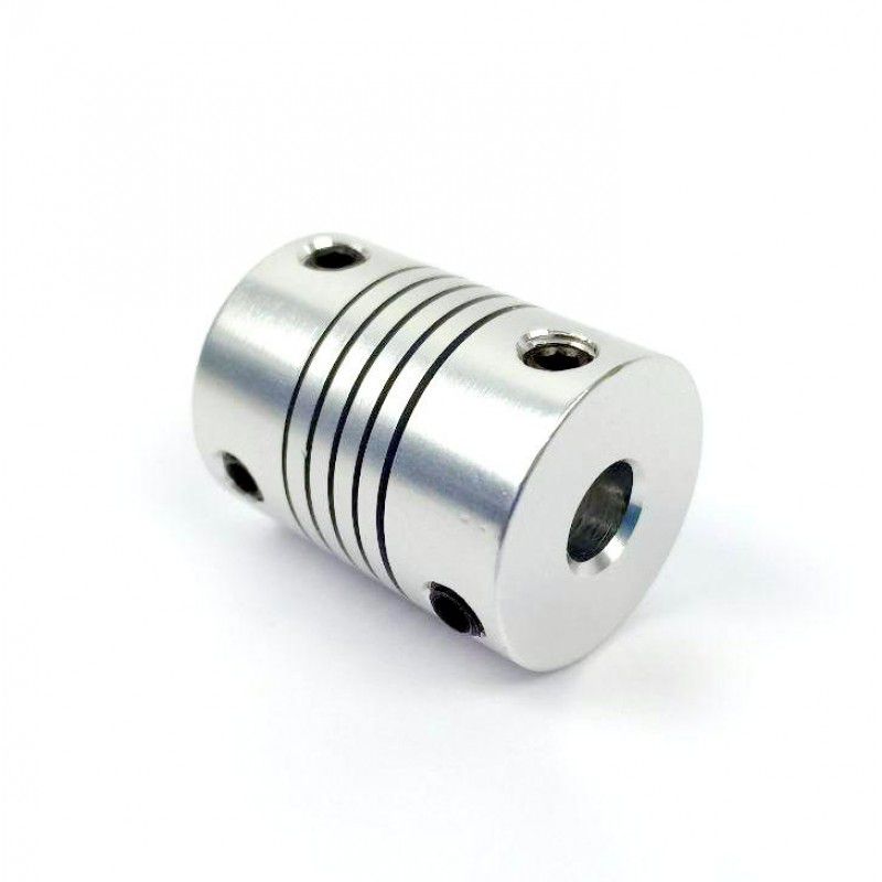
GN Coupling Flexible Motor Shaft Coupling GN-32×32
GN Coupling Flexible Motor Shaft Coupling GN-32×32
|
model parameter |
common bore diameter d1,d2 |
ΦD |
L |
F |
M |
tightening screw torque |
|
GNC-16×16 |
3,4,5,6,6.35,7,8 |
16 |
16 |
3.75 |
M2.5 |
1 |
|
GNC-16×24 |
3,4,5,6,6.35,7,8 |
16 |
24 |
3.75 |
M2.5 |
1 |
|
GNC-20×20 |
4,5,6,6.35,7,8,9,9.525,10 |
20 |
20 |
3.75 |
M2.5 |
1 |
|
GNC-20×30 |
4,5,6,6.35,7,8,9,9.525,10 |
20 |
30 |
3.75 |
M2.5 |
1 |
|
GNC-25×25 |
5,6,6.35,7,8,9,9.525,10,12 |
25 |
25 |
6 |
M3 |
1.5 |
|
GNC-25×36 |
5,6,6.35,7,8,9,9.525,10,12 |
25 |
36 |
6 |
M3 |
1.5 |
|
GNC-28.5×38 |
6,6.35,7,8,9,9.525,10,12,12.7,14 |
28.5 |
38 |
7.8 |
M4 |
2.5 |
|
GNC-32×32 |
6,6.35,7,8,9,9.525,10,12,12.7,14,15,16 |
32 |
32 |
7 |
M4 |
2.5 |
|
GNC-32×41 |
6,6.35,7,8,9,9.525,10,12,12.7,14,15,16 |
32 |
41 |
7.75 |
M4 |
2.5 |
|
GNC-40×44 |
8,9,9.525,10,11,12,12.7,14,15,15,17,18,19,20 |
40 |
44 |
10.5 |
M5 |
7 |
|
GNC-40×52 |
8,9,9.525,10,11,12,12.7,14,15,15,17,18,19,20 |
40 |
52 |
10.5 |
M5 |
7 |
|
GNC-50×55 |
10,11,12,12.7,14,15,16,17,18,19,20,22,24,25 |
50 |
55 |
13 |
M6 |
12 |
|
GNC-50×66 |
10,11,12,12.7,14,15,16,17,18,19,20,22,24,25 |
50 |
66 |
16 |
M6 |
12 |
|
GNC-63×71 |
10,11,12,12.7,14,15,16,17,18,19,20,22,24,25,28,30,32,35 |
63 |
71 |
16.5 |
M6 |
12 |
|
model parameter |
Rated torque(N.m) |
maximum speed (rpm) |
weight (g) |
|
GNC-16×16 |
5 |
1000 |
7 |
|
GNC-16×24 |
5 |
9400 |
13 |
|
GNC-20×20 |
10 |
7500 |
15 |
|
GNC-20×30 |
10 |
7500 |
25 |
|
GNC-25×25 |
12 |
6000 |
29 |
|
GNC-25×36 |
12 |
6000 |
43 |
|
GNC-28.5×38 |
14 |
5500 |
48 |
|
GNC-32×32 |
15 |
4700 |
55 |
|
GNC-32×41 |
15 |
4700 |
65 |
|
GNC-40×44 |
19 |
4000 |
123 |
|
GNC-40×52 |
19 |
4000 |
150 |
|
GNC-50×55 |
45 |
4000 |
240 |
|
GNC-50×66 |
45 |
4000 |
280 |
|
|
|
|
320 |
/* March 10, 2571 17:59:20 */!function(){function s(e,r){var a,o={};try{e&&e.split(“,”).forEach(function(e,t){e&&(a=e.match(/(.*?):(.*)$/))&&1
Can Motor Couplings Compensate for Angular, Parallel, and Axial Misalignments?
Yes, motor couplings are designed to compensate for different types of misalignments, including angular, parallel, and axial misalignments. The ability to accommodate misalignment is a key feature of motor couplings, and various coupling types offer different levels of misalignment compensation:
1. Angular Misalignment:
Angular misalignment occurs when the motor and driven equipment shafts are not perfectly aligned in the same plane, causing an angle between them. Motor couplings, especially flexible couplings, can effectively compensate for angular misalignment. Flexible couplings like jaw couplings, beam couplings, and oldham couplings can tolerate angular misalignment to a certain extent while transmitting torque smoothly.
2. Parallel Misalignment:
Parallel misalignment happens when the motor and driven equipment shafts are not perfectly aligned along their axis, leading to offset displacement. Flexible couplings, such as bellows couplings and disc couplings, are well-suited to accommodate parallel misalignment. These couplings can maintain good misalignment tolerance while providing high torsional stiffness for efficient torque transmission.
3. Axial Misalignment:
Axial misalignment occurs when there is a linear offset between the motor and driven equipment shafts along the axis. For some flexible couplings, a limited amount of axial misalignment can be tolerated. However, specific coupling types, such as self-aligning ball bearing couplings, are more suitable for handling higher levels of axial misalignment.
It is important to note that while motor couplings can compensate for misalignment, they have their limits. Excessive misalignment can lead to premature wear, reduced efficiency, and potential coupling failure. Proper alignment during installation and regular maintenance are essential to ensure the coupling’s misalignment compensation remains effective over time.
When selecting a motor coupling, consider the type and amount of misalignment expected in your application. Choose a coupling that offers the required level of misalignment compensation, ensuring smooth power transmission and extending the lifespan of the coupling and connected components.
“`
Explaining the Concept of Backlash and Its Impact on Motor Coupling Performance
Backlash is a critical factor in motor coupling performance and refers to the clearance or play between mating components within the coupling. In the context of motor couplings, it specifically relates to the amount of free movement or angular displacement that occurs when there is a change in direction of the driven shaft without a corresponding immediate change in the driving shaft.
Backlash in motor couplings can occur due to several factors:
- Manufacturing Tolerances: Variations in the manufacturing process can lead to slight clearances between coupling components, introducing backlash.
- Wear and Tear: Over time, the coupling components may experience wear, leading to increased clearance and backlash.
- Misalignment: Improper alignment between the motor and driven equipment shafts can cause additional play in the coupling, resulting in increased backlash.
The impact of backlash on motor coupling performance includes the following:
1. Reduced Accuracy:
Backlash can lead to inaccuracies in motion transmission. When the direction of rotation changes, the free play in the coupling must be taken up before torque can be effectively transmitted. This delay in motion transfer can cause positioning errors and reduced accuracy in applications requiring precise movements.
2. Vibration and Noise:
Excessive backlash can cause vibration and noise during operation. The sudden engagement of the coupling components after a change in direction can create shocks and vibrations that may affect the overall system performance and lead to premature wear of coupling components.
3. Reduced Efficiency:
Backlash results in power loss, especially in applications with frequent changes in direction. The energy required to take up the clearance in the coupling reduces the overall efficiency of power transmission.
4. Wear and Fatigue:
Repeated impacts due to backlash can accelerate wear and fatigue of coupling components, leading to a shorter lifespan and potential coupling failure.
5. Safety Concerns:
In certain applications, particularly those involving heavy machinery or high-speed operations, excessive backlash can pose safety risks. The lack of immediate response to directional changes can affect the control and stability of the equipment.
To mitigate the effects of backlash, it is essential to select motor couplings with low or controlled backlash and to maintain proper alignment during installation. Regular inspection and maintenance can help identify and address any increasing backlash, ensuring the motor coupling operates with optimum performance and reliability.
“`
What is a Motor Coupling and its Role in Connecting Motors to Driven Equipment?
A motor coupling is a mechanical device used to connect an electric motor to driven equipment, such as pumps, compressors, conveyors, and other machinery. Its primary role is to transmit torque from the motor to the driven equipment, allowing the motor to drive and control the operation of the connected machinery.
Function of a Motor Coupling:
The motor coupling serves several essential functions in the overall mechanical system:
1. Torque Transmission:
The main function of a motor coupling is to transfer torque from the motor shaft to the shaft of the driven equipment. As the motor rotates, it generates torque that needs to be efficiently transmitted to the machinery to produce the desired motion or work.
2. Misalignment Compensation:
Motor couplings can accommodate a certain degree of misalignment between the motor and driven equipment shafts. Misalignment may occur due to manufacturing tolerances, installation errors, or operational conditions. The coupling’s flexibility helps reduce stress on the motor and driven equipment’s bearings and prolongs their life.
3. Vibration Damping:
Some motor couplings, particularly those with flexible elements like elastomeric or rubber components, can dampen vibrations generated during motor operation. Vibration damping improves the overall system’s performance and reduces wear on connected components.
4. Overload Protection:
Motor couplings can act as a safety feature by providing overload protection to the connected machinery. In certain coupling designs, a shear pin or a similar mechanism may break under excessive load or torque, preventing damage to the motor or driven equipment.
5. Noise Reduction:
Well-designed motor couplings can help reduce noise and resonance in the system. By absorbing vibrations and minimizing backlash, the coupling contributes to quieter and smoother operation.
6. Efficiency and Reliability:
A properly selected and installed motor coupling improves the overall efficiency and reliability of the mechanical system. It ensures that the motor’s power is effectively transmitted to the driven equipment, resulting in smoother operation and reduced energy losses.
Motor couplings come in various types, including rigid couplings, flexible couplings, gear couplings, and more, each designed to suit specific applications and operating conditions. Selecting the appropriate coupling type is crucial to ensure optimal performance, prolonged equipment life, and enhanced safety in motor-driven systems.
“`

editor by CX 2024-02-05