
Product Description
Hot sale: low noise,no leakage, no additional cost for pump motor coupling electric motor coupling magnetic coupling principle
Please send us following information.
1. Motor output power(KW)
2. Motor speed(RPM)
3. Torque of the mangetic coupling
4. Working pressure of the housing(isolation sleeve)
5. Working temperature of magnetic coupling
6. Technical drawing of the output part connector (usually motor)
7. Technical drawing of the input part connector (usually pump)
Introduction of pump motor coupling electric motor coupling magnetic coupling principle
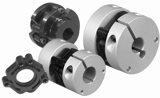
Magnetic shaft coupling is a new kind of coupling, which connects motor and machine by permanent magnetic force.
They are consisted of external rotor, internal rotor and isolating covers.
They work in the sealed magnetic drive pumps, which transporting volatile, flammable, explosive and toxic solutions with no leakage.
These magnetic shaft couplings can be used to connect gear pumps , screw pumps, centrifugal pumps, etc. with all types of electric motor or gear box.
Magnetic shaft coupling are widely used in various industries and fields, such as chemical, papermaking, foodstuff, pharmacy, and so on.
Advantages of pump motor coupling electric motor coupling magnetic coupling principle
» Elimination of fluid leakage from the pump shaft.
» Vibrations are not transmitted to the pump.
» No maintenance required for magnetic couplings.
» Using magnetic couplings allows use of standard pumps without expensive mechanical seals.
» No additional cost for purchasing mechanical seal spare parts and maintenance.
Technical drawing of pump motor coupling electric motor coupling magnetic coupling principle
Specification of pump motor coupling electric motor coupling magnetic coupling principle
| Item | Internal Rotor(mm) | External Rotor(mm) | Isolating Covering(mm) | |||||||||||||||||
| A | B | C | D | E | F | G | Shaft Pin | H | I | J | L | N | M | P | Q | R | S | T | U | |
| GME03-3LM00 | Φ35 | – | Φ10 | 26 | – | 18 | – | M6X12 | Φ42 | Φ60 | Φ50 | 46 | 6-M4 | Φ40 | Φ50 | 4-Φ5.4 | Φ38 | Φ60 | 6 | 6 |
| GME03-5MM00 | Φ42 | – | Φ12 | 27 | 4 | 18 | 13.8 | M6X16 | Φ49 | Φ72 | Φ60 | 46 | 4-Φ6.7 | Φ52 | Φ60 | 4-Φ6.7 | Φ44 | Φ74 | 8 | 8 |
| GME03-16LM00 | Φ56 | – | Φ12 | 45 | 4 | 25 | 13.8 | M6X16 | Φ63 | Φ89 | Φ80 | 75 | 6-M5 | Φ70 | Φ75 | 4-Φ6.7 | Φ58 | Φ89 | 8 | 8 |
| GME03-16LM01 | Φ56 | – | Φ12 | 45 | 4 | 25 | 13.8 | M6X16 | Φ63 | Φ89 | Φ80 | 75 | 4-M5 | Φ70 | Φ75 | 4-Φ6.7 | Φ58 | Φ89 | 6 | 10 |
| GME03-16MM00 | Φ56 | – | Φ12 | 45 | 4 | 25 | 13.8 | M6X16 | Φ63 | Φ89 | Φ80 | 75 | 6-M5 | Φ70 | Φ75 | 4-Φ6.7 | Φ58 | Φ89 | 8 | 8 |
| GME03-22LM00 | Φ88 | – | Φ20 | 29 | 6 | 25 | 22.8 | M8X20 | Φ97 | Φ122 | Φ110 | 70 | 8-M6 | Φ98 | Φ108 | 6-Φ6.7 | Φ91 | Φ122 | 8 | 8 |
| GME03-30LM00 | Φ88 | – | Φ20 | 48 | 6 | 30 | 22.8 | M8X20 | Φ97 | Φ122 | Φ110 | 81 | 8-M6 | Φ98 | Φ108 | 6-Φ6.7 | Φ91 | Φ122 | 8 | 8 |
| GME03-40LM00 | Φ101 | – | Φ25 | 49 | 8 | 28 | 28.3 | M10X20 | Φ109 | Φ140 | Φ124 | 83 | 8-M8 | Φ110 | Φ126 | 8-Φ6.7 | Φ103 | Φ140 | 12 | 6 |
| GME03-50LM00 | Φ107 | – | Φ20 | 70 | 6 | 30 | 22.8 | M6X16 | Φ113.4 | Φ145 | Φ135 | 80 | 4-M6 | Φ126 | Φ133 | 12-Φ8.7 | Φ109 | Φ153 | 12 | 15 |
| GME03-65LM00 | Φ101 | – | Φ25 | 77 | 8 | 45 | 28.3 | M10X20 | Φ109 | Φ140 | Φ124 | 111 | 8-M8 | Φ110 | Φ126 | 8-Φ6.7 | Φ103 | Φ140 | 12 | 6 |
| GME03-80LM00 | Φ106 | – | Φ32 | 65 | 10 | 21 | 36.5 | M6X25 | Φ115 | Φ145 | Φ135 | 82 | 4-M6 | Φ127 | Φ135 | 6-Φ8.7 | Φ110 | Φ153 | 13 | 18 |
| GME03-80LM00 | Φ141 | Φ92 | Φ40 | 65 | 12 | 45 | 43.3 | M12X25 | Φ152 | Φ180 | Φ168 | 100 | 8-M8 | Φ154 | Φ164 | 8-Φ6.7 | Φ145 | Φ180 | 12 | 8 |
| GME03-100LM00 | Φ131 | Φ82 | Φ32 | 80 | 10 | 24.5 | 35.3 | M8X35 | Φ139 | Φ170 | Φ160 | 100 | 4-M6 | Φ152 | Φ158 | 8-Φ8.7 | Φ133 | Φ178 | 14 | 21 |
| GME03-110LH00 | Φ141 | Φ92 | Φ40 | 85 | 10 | 50 | 43.3 | M12X25 | Φ152 | Φ184 | Φ168 | 115 | 12-M8 | Φ156 | Φ164 | 12-Φ6.7 | Φ145 | Φ180 | 12 | 3 |
| GME03-110LM00 | Φ141 | Φ92 | Φ35 | 80 | 10 | 55 | 38.3 | M12X25 | Φ152 | Φ180 | Φ168 | 115 | 12-M8 | Φ154 | Φ164 | 12-Φ6.7 | Φ145 | Φ180 | 12 | 3 |
| GME03-140LM00 | Φ141 | Φ92 | Φ40 | 110 | 12 | 80 | 43.3 | M12X25 | Φ152 | Φ190 | Φ170 | 145 | 12-M10 | Φ154 | Φ164 | 12-Φ6.7 | Φ145 | Φ180 | 12 | 3 |
| GME03-180LM00 | Φ141 | Φ92 | Φ40 | 140 | 12 | 95 | 43.3 | M12X25 | Φ152 | Φ190 | Φ170 | 175 | 12-M10 | Φ154 | Φ164 | 12-Φ6.7 | Φ145 | Φ180 | 12 | 3 |
| GME03-220LM00 | Φ141 | Φ92 | Φ48 | 160 | 14 | 110 | 51.8 | M12X25 | Φ152 | Φ190 | Φ170 | 195 | 12-M10 | Φ154 | Φ164 | 12-Φ6.7 | Φ145 | Φ180 | 12 | 3 |
| GME03-300LM00 | Φ162 | – | Φ65 | 100 | 18 | 60 | 69.4 | Φ170 | Φ198 | Φ188 | 123 | 12-M6 | Φ180 | Φ192 | 12-Φ11 | Φ163.5 | Φ218 | 16 | 10 | |
| GME03-400LH00 | Φ195 | – | Φ70 | 127 | 20 | 107 | 79.9 | M12X25 | Φ203 | Φ234 | Φ222 | 152 | 6-M6 | Φ212 | Φ164 | 12-Φ11 | Φ198 | Φ278 | 16 | 22 |
Application of pump motor coupling electric motor coupling magnetic coupling principle
The ability to hermetically separate 2 areas whilst continuing to transmit mechanical power from one to the other makes these couplings ideal for applications where prevention of cross contamination is essential. For instance: hydraulic sectors, dosing systems, compressors, sterilizers, industrial ovens, biotechnology, subsea equipment, pharmaceutical industry, chemical industry, food industry, generators and mixers.
Operation principles of pump motor coupling electric motor coupling magnetic coupling principle
The magnetic coupling works by using the power generated by permanent magnets. No external power supply is needed. These are permanent magnets not electro magnets.
Packing Method of pump motor coupling electric motor coupling magnetic coupling principle
Double strength corrugated Carton and Wood case Sea Packing.
Understanding the Torque and Misalignment Capabilities of Motor Couplings
Motor couplings play a crucial role in transmitting torque from the motor to the driven equipment while accommodating certain degrees of misalignment between the shafts. Here’s a detailed explanation of their torque and misalignment capabilities:
Torque Transmission:
Torque transmission is one of the primary functions of a motor coupling. It refers to the ability of the coupling to transfer rotational force (torque) from the motor shaft to the driven equipment shaft. The torque capacity of a coupling depends on various factors, including:
- Coupling Type: Different coupling types have varying torque capacities. For instance, gear couplings have high torque capacity, making them suitable for heavy-duty applications.
- Material and Design: The material and design of the coupling elements play a role in determining its torque capacity. Couplings made from high-strength materials can handle higher torque loads.
- Size: The size of the coupling affects its torque capacity. Larger couplings generally have higher torque ratings.
- Operating Conditions: Environmental factors, temperature, and speed also influence the torque capacity of the coupling.
Misalignment Compensation:
Motor couplings are designed to accommodate a certain degree of misalignment between the motor and driven equipment shafts. Misalignment can occur due to factors such as manufacturing tolerances, thermal expansion, and operational conditions. The misalignment capability of a coupling depends on its type and design:
- Flexible Couplings: Flexible couplings, such as jaw couplings or elastomeric couplings, can handle both angular and parallel misalignment. They provide some flexibility to dampen vibrations and compensate for minor misalignment.
- Universal Joints: Universal joints can handle angular misalignment and are commonly used in applications requiring a high range of motion, such as vehicle drivelines.
- Disc Couplings: Disc couplings can handle angular misalignment and provide high torsional stiffness for precision applications.
- Bellows Couplings: Bellows couplings are suitable for applications requiring high levels of parallel misalignment compensation, such as in optical equipment.
It is essential to consider the torque and misalignment requirements of the specific application when selecting a motor coupling. Properly matching the coupling’s capabilities to the system’s needs ensures efficient torque transmission and helps prevent premature wear or failure due to misalignment issues.
“`
Specific Safety Precautions When Working with Motor Couplings
Working with motor couplings involves handling mechanical components and power transmission systems, which can pose certain safety risks. It is essential to follow specific safety precautions to prevent accidents and ensure the well-being of personnel. Here are some safety measures to consider:
1. Lockout/Tagout Procedures:
Prior to any maintenance or installation work on motor couplings, follow lockout/tagout procedures to isolate the power source and prevent accidental startup. This ensures the motor and equipment are de-energized, reducing the risk of electrical hazards.
2. Personal Protective Equipment (PPE):
Wear appropriate personal protective equipment, including safety goggles, gloves, and steel-toed shoes, when working with motor couplings. PPE provides protection against potential hazards such as flying debris or pinch points.
3. Proper Lifting Techniques:
When handling heavy couplings or equipment, use proper lifting techniques to avoid strain or injury. Seek assistance if needed to lift and position larger components safely.
4. Inspect Coupling Condition:
Before any work, inspect the coupling for signs of wear, damage, or misalignment. Do not work with a damaged coupling, as it may compromise system integrity and safety.
5. Avoid Excessive Force:
Avoid applying excessive force or using tools that are not appropriate for the job when installing or removing couplings. Excessive force can lead to component failure or personal injury.
6. Follow Manufacturer Guidelines:
Adhere to the manufacturer’s guidelines and instructions during installation, maintenance, and troubleshooting processes. Manufacturer recommendations are designed to ensure safe and proper operation.
7. Regular Inspection and Maintenance:
Implement regular inspection and maintenance schedules for motor couplings and associated equipment. Identify and address any issues promptly to prevent potential hazards or failures.
8. Keep Work Area Clean:
Keep the work area clean and free of clutter. A tidy workspace reduces the risk of accidents and improves overall efficiency.
9. Avoid Contact with Rotating Components:
When the motor is energized, avoid contact with rotating coupling components to prevent injury. Ensure the system is de-energized during maintenance tasks.
10. Training and Competence:
Ensure that personnel working with motor couplings are adequately trained and competent in the procedures and safety measures related to coupling installation, maintenance, and operation.
By following these safety precautions, you can minimize risks and create a safer working environment when handling motor couplings and associated power transmission systems.
“`
What is a Motor Coupling and its Role in Connecting Motors to Driven Equipment?
A motor coupling is a mechanical device used to connect an electric motor to driven equipment, such as pumps, compressors, conveyors, and other machinery. Its primary role is to transmit torque from the motor to the driven equipment, allowing the motor to drive and control the operation of the connected machinery.
Function of a Motor Coupling:
The motor coupling serves several essential functions in the overall mechanical system:
1. Torque Transmission:
The main function of a motor coupling is to transfer torque from the motor shaft to the shaft of the driven equipment. As the motor rotates, it generates torque that needs to be efficiently transmitted to the machinery to produce the desired motion or work.
2. Misalignment Compensation:
Motor couplings can accommodate a certain degree of misalignment between the motor and driven equipment shafts. Misalignment may occur due to manufacturing tolerances, installation errors, or operational conditions. The coupling’s flexibility helps reduce stress on the motor and driven equipment’s bearings and prolongs their life.
3. Vibration Damping:
Some motor couplings, particularly those with flexible elements like elastomeric or rubber components, can dampen vibrations generated during motor operation. Vibration damping improves the overall system’s performance and reduces wear on connected components.
4. Overload Protection:
Motor couplings can act as a safety feature by providing overload protection to the connected machinery. In certain coupling designs, a shear pin or a similar mechanism may break under excessive load or torque, preventing damage to the motor or driven equipment.
5. Noise Reduction:
Well-designed motor couplings can help reduce noise and resonance in the system. By absorbing vibrations and minimizing backlash, the coupling contributes to quieter and smoother operation.
6. Efficiency and Reliability:
A properly selected and installed motor coupling improves the overall efficiency and reliability of the mechanical system. It ensures that the motor’s power is effectively transmitted to the driven equipment, resulting in smoother operation and reduced energy losses.
Motor couplings come in various types, including rigid couplings, flexible couplings, gear couplings, and more, each designed to suit specific applications and operating conditions. Selecting the appropriate coupling type is crucial to ensure optimal performance, prolonged equipment life, and enhanced safety in motor-driven systems.
“`

editor by CX 2023-11-16