
Product Description
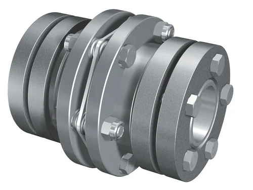
JMI Type Diaphragm Coupling(JB/T9147-1999)
JM Series Diaphragm Coupling of flexible metal flexible coupling, which relies on the metal diaphragm to transmit torque from the main connection, motivation, has the advantages of elastic damping and no lubrication, no noise, is an ideal product for replacing the gear coupling and coupling current. It can compensate for the axial, radial, and angular deviation caused by the manufacturing error, installation error, bearing deformation, and the change in temperature rise.
Features
1. Compensation two-axis misalignment of the ability, and tooth type coupling can be much more than a double angle displacement, radial displacement of the small, flexible, allowing a certain axial, radial, and angular displacement.
2. Obvious damping effect, no noise, no wear, and tear.
3. High transmission efficiency, up to 99.86%. Especially suitable for medium and high-speed high-power transmission.
4. Adapt to high temperature (-80+300) and harsh environments, and can be in shock, vibration, safety, and dynamic conditions.
5. Simple structure, lightweight, small size, convenient assembly, and disassembly. Without moving the machine can be disassembled (with intermediate type), with no need for lubrication.
6. Accurately convey the rotational speed, the operation has not turned bad, can be used for the transmission of precision machinery.
JM series diaphragm flexible coupling is widely used in the machinery and equipment industry, metallurgy, mines, petroleum, chemical, electric power, shipbuilding, lifting transport, textile, light industry, agricultural machinery, printing machinery, and water pump, fan, etc. in the transmission of power machine.
JMI Type Coupling Main Dimension(JB/T9147-1999)
| Type | Nominal torque Tn |
Peak torque Tmax |
Max Speed np |
Bore diameter d |
Bore Length | D | t | Torsional stiffness C |
Mass | Rotary inertia | |||
| Y type | J,J1,Z,Z1 type | L(recommend) | |||||||||||
| L | L | L1 | |||||||||||
| N·m | N·m | r·min-1 | mm | N·m/rad | kg | kg·m2 | |||||||
| JMI1 | 25 | 80 | 6000 | 14 | 32 | – | J127 Z120 |
35 | 90 | 8.8 | 1×10⁴ | 1 | 0.0007 |
| 16,18,19 | 42 | 30 | |||||||||||
| 20,22 | 52 | 38 | |||||||||||
| JMI2 | 63 | 180 | 5000 | 18,19 | 42 | 30 | 45 | 100 | 9.5 | 1.4×10⁴ | 2.3 | 0.001 | |
| 20,22,24 | 52 | 38 | |||||||||||
| 25 | 62 | 44 | |||||||||||
| JMI3 | 100 | 315 | 5000 | 20,22,24 | 52 | – | 38 | 50 | 120 | 11 | 1.87×10⁴ | 2.3 | 0.0571 |
| 25,28 | 62 | 44 | |||||||||||
| 30 | 82 | 60 | |||||||||||
| JMI4 | 160 | 500 | 4500 | 24 | 52 | 38 | 55 | 130 | 12.5 | 3.12×10⁴ | 3.3 | 0.0571 | |
| 25,28 | 62 | 44 | |||||||||||
| 30,32,35 | 82 | 60 | |||||||||||
| JMI5 | 250 | 710 | 4000 | 28 | 62 | 44 | 60 | 150 | 14 | 4.32×10⁴ | 5.3 | 0.0083 | |
| 30,32,35,38 | 82 | 60 | |||||||||||
| 40 | 112 | 84 | |||||||||||
| JMI6 | 400 | 1120 | 3600 | 32,35,38 | 82 | 82 | 60 | 65 | 170 | 15.5 | 6.88×10⁴ | 8.7 | 0.0159 |
| 40,42,45,48, 50 |
112 | 112 | 84 | ||||||||||
| JMI7 | 630 | 1800 | 3000 | 40,42,45,48, 50,55,56 |
112 | 112 | 84 | 70 | 210 | 19 | 10.35×10⁴ | 14.3 | 0.571 |
| 60 | 142 | – | 107 | ||||||||||
| JMI8 | 1000 | 2500 | 2800 | 45,48,50,55, 56 |
112 | 112 | 84 | 80 | 240 | 22.5 | 16.11×10⁴ | 22 | 0. 0571 |
| 60,63,65,70 | 142 | 107 | |||||||||||
| JMI9 | 1600 | 4000 | 2500 | 55,56 | 112 | 84 | 85 | 260 | 24 | 26.17×10⁴ | 29 | 0.1415 | |
| 60,63,70,71, 75 |
142 | 107 | |||||||||||
| 80 | 172 | 132 | |||||||||||
| JMI10 | 2500 | 6300 | 2000 | 63,65,70,71,75 | 142 | 142 | 107 | 90 | 280 | 17 | 7.88×10⁴ | 52 | 0.2974 |
| 80,85,90,95 | 172 | – | 132 | ||||||||||
| JMI11 | 4000 | 9000 | 1800 | 75 | 142 | 142 | 107 | 95 | 300 | 19.5 | 10.49×10⁴ | 69 | 0.4782 |
| 80,85,90,95 | 172 | 172 | 132 | ||||||||||
| 100,110 | 212 | – | 167 | ||||||||||
| JMI12 | 6300 | 12500 | 1600 | 90,95 | 172 | 132 | 120 | 340 | 23 | 14.07×10⁴ | 94 | 0.8067 | |
| 100,110,120,125 | 212 | 167 | |||||||||||
| JMI13 | 10000 | 18000 | 1400 | 100,110,120,125 | 212 | 167 | 135 | 380 | 28 | 19.2×10⁴ | 128 | 1.7053 | |
| 130,140 | 252 | 202 | |||||||||||
| JMI14 | 16000 | 28000 | 1200 | 120,125 | 212 | – | 167 | 150 | 420 | 31 | 30.0×10⁴ | 184 | 2.6832 |
| 130,140,150 | 252 | 202 | |||||||||||
| 160 | 302 | 242 | |||||||||||
| JMI15 | 25000 | 40000 | 1120 | 140,150 | 252 | 202 | 180 | 480 | 37.5 | 47.46×10⁴ | 262 | 4.8015 | |
| 160,170,180 | 302 | 242 | |||||||||||
| JMI16 | 40000 | 56000 | 1000 | 160,170,180 | 302 | 242 | 200 | 560 | 41 | 48.09×10⁴ | 384 | 9.4118 | |
| 190,200 | 352 | 282 | |||||||||||
| JMI17 | 63000 | 80000 | 900 | 190,200,220 | 352 | 282 | 220 | 630 | 47 | 10.13×10⁴ | 561 | 18.3753 | |
| 240 | 410 | 330 | |||||||||||
| JMI18 | 100000 | 125000 | 800 | 220 | 352 | 282 | 250 | 710 | 54.5 | 16.14×10⁴ | 723 | 28.2033 | |
| 240,250,260 | 410 | 330 | |||||||||||
| JMI19 | 160000 | 200000 | 710 | 250,260 | 410 | 330 | 280 | 800 | 48 | 79.8×10⁴ | 1267 | 66.5813 | |
| 280,300,320 | 470 | 380 | |||||||||||
♦Product Show
♦Other Products List
| Transmission Machinery Parts Name |
Model |
| Universal Coupling | WS, WSD, WSP |
| Cardan Shaft | SWC,SWP,SWZ |
| Tooth Coupling | CL,CLZ,GCLD,GIICL, GICL,NGCL,GGCL,GCLK |
| Disc Coupling | JMI, JMIJ, JMII, JMIIJ |
| High Flexible Coupling | LM |
| Chain Coupling | GL |
| Jaw Coupling | LT |
| Grid Coupling | JS |
♦Our Company
HangZhou CHINAMFG Machinery Manufacturing Co., Ltd. is a high-tech enterprise specializing in the design and manufacture of various types of coupling. There are 86 employees in our company, including 2 senior engineers and no fewer than 20 mechanical design and manufacture, heat treatment, welding, and other professionals.
Advanced and reasonable process, complete detection means. Our company actively introduces foreign advanced technology and equipment, on the basis of the condition, we make full use of the advantage and do more research and innovation. Strict to high quality and operate strictly in accordance with the ISO9000 quality certification system standard mode.
Our company supplies different kinds of products. High quality and reasonable price. We stick to the principle of “quality first, service first, continuous improvement and innovation to meet the customers” for the management and “zero defect, zero complaints” as the quality objective.
♦Our Services
1. Design Services
Our design team has experience in Cardan shafts relating to product design and development. If you have any needs for your new product or wish to make further improvements, we are here to offer our support.
2. Product Services
raw materials → Cutting → Forging →Rough machining →Shot blasting →Heat treatment →Testing →Fashioning →Cleaning→ Assembly→Packing→Shipping
3. Samples Procedure
We could develop the sample according to your requirement and amend the sample constantly to meet your need.
4. Research & Development
We usually research the new needs of the market and develop new models when there are new cars in the market.
5. Quality Control
Every step should be a special test by Professional Staff according to the standard of ISO9001 and TS16949.
♦FAQ
Q 1: Are you a trading company or a manufacturer?
A: We are a professional manufacturer specializing in manufacturing
various series of couplings.
Q 2:Can you do OEM?
Yes, we can. We can do OEM & ODM for all the customers with customized artworks in PDF or AI format.
Q 3:How long is your delivery time?
Generally, it is 20-30 days if the goods are not in stock. It is according to quantity.
Q 4: Do you provide samples? Is it free or extra?
Yes, we could offer the sample but not for free. Actually, we have a very good price principle, when you make the bulk order the cost of the sample will be deducted.
Q 5: How long is your warranty?
A: Our Warranty is 12 months under normal circumstances.
Q 6: What is the MOQ?
A: Usually our MOQ is 1pcs.
Q 7: Do you have inspection procedures for coupling?
A:100% self-inspection before packing.
Q 8: Can I have a visit to your factory before the order?
A: Sure, welcome to visit our factory.
Q 9: What’s your payment?
A:1) T/T.
♦Contact Us
Web: huadingcoupling
Add: No.11 HangZhou Road,Chengnan park,HangZhou City,ZheJiang Province,China
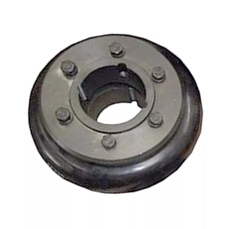
How do you install and align a flexible coupling properly to ensure optimal performance?
Proper installation and alignment of a flexible coupling are essential to ensure its optimal performance and longevity. Incorrect installation can lead to premature wear, increased vibrations, and potential equipment failure. Below are the steps to install and align a flexible coupling properly:
1. Pre-Installation Inspection:
Before installation, inspect the flexible coupling and its components for any visible damage or defects. Check that the coupling’s size and specifications match the application requirements. Ensure that the shafts and equipment connected to the coupling are clean and free from debris.
2. Shaft Preparation:
Prepare the shafts by removing any oil, grease, or contaminants from the surfaces that will come into contact with the coupling. Ensure that the shaft ends are smooth and free from burrs that could affect the fit of the coupling.
3. Coupling Hub Installation:
Slide the coupling hubs onto the shafts, ensuring they are positioned securely and evenly on each shaft. Use a lubricant recommended by the manufacturer to facilitate the installation and ensure a proper fit.
4. Alignment:
Proper alignment is critical for the performance and longevity of the flexible coupling. Align the shafts by checking both angular and parallel misalignment. Utilize precision alignment tools, such as dial indicators or laser alignment systems, to achieve accurate alignment. Follow the manufacturer’s alignment specifications and tolerance limits.
5. Tightening Fasteners:
Once the shafts are properly aligned, tighten the coupling’s fasteners to the manufacturer’s recommended torque values. Gradually tighten the fasteners in a cross pattern to ensure even distribution of the load on the coupling hubs. Avoid over-tightening, as it may cause distortion or damage to the coupling.
6. Run-Out Check:
After installation, perform a run-out check to verify that the coupling’s rotating components are balanced and aligned. Excessive run-out can lead to vibrations and reduce the coupling’s performance. If significant run-out is detected, recheck the alignment and address any issues that may be causing it.
7. Lubrication:
Ensure that the flexible coupling is adequately lubricated, following the manufacturer’s recommendations. Proper lubrication reduces friction and wear, enhancing the coupling’s efficiency and reliability.
8. Periodic Inspection and Maintenance:
Regularly inspect the flexible coupling for signs of wear, misalignment, or damage. Address any issues promptly to prevent further problems. Depending on the coupling type and application, scheduled maintenance may include re-greasing, re-alignment, or replacing worn components.
Summary:
Proper installation and alignment are crucial for ensuring the optimal performance and longevity of a flexible coupling. Following the manufacturer’s guidelines, inspecting the components, achieving accurate alignment, and using the appropriate lubrication are key steps in the installation process. Regular inspection and maintenance help to identify and address potential issues, ensuring the coupling continues to operate smoothly and efficiently in the mechanical system.
Can flexible couplings be used in power generation equipment, such as turbines and generators?
Yes, flexible couplings are commonly used in power generation equipment, including turbines and generators. These critical components of power generation systems require reliable and efficient shaft connections to transfer power from the prime mover (e.g., steam turbine, gas turbine, or internal combustion engine) to the electricity generator.
Flexible couplings play a vital role in power generation equipment for the following reasons:
- Misalignment Compensation: Power generation machinery often experiences misalignment due to factors like thermal expansion, settling, and foundation shifts. Flexible couplings can accommodate these misalignments, reducing the stress on shafts and minimizing wear on connected components.
- Vibration Dampening: Turbines and generators can generate significant vibrations during operation. Flexible couplings help dampen these vibrations, reducing the risk of resonance and excessive mechanical stress on the system.
- Torsional Shock Absorption: Power generation equipment may encounter torsional shocks during startup and shutdown processes. Flexible couplings can absorb and dissipate these shocks, protecting the entire drivetrain from damage.
- Isolation of High Torque Loads: Some power generation systems may have torque fluctuations during operation. Flexible couplings can isolate these fluctuations, preventing them from propagating to other components.
- Electrical Isolation: In certain cases, flexible couplings with non-metallic elements can provide electrical isolation, preventing the transmission of electrical currents between shafts.
Power generation applications impose specific requirements on flexible couplings, such as high torque capacity, robust construction, and resistance to environmental factors like temperature and humidity. Different types of flexible couplings, including elastomeric, metallic, and composite couplings, are available to meet the varying demands of power generation equipment.
When selecting a flexible coupling for power generation equipment, engineers must consider factors such as the type of prime mover, torque and speed requirements, operating conditions, and the specific application’s environmental challenges. Consulting with coupling manufacturers and following their engineering recommendations can help ensure the appropriate coupling is chosen for each power generation system.
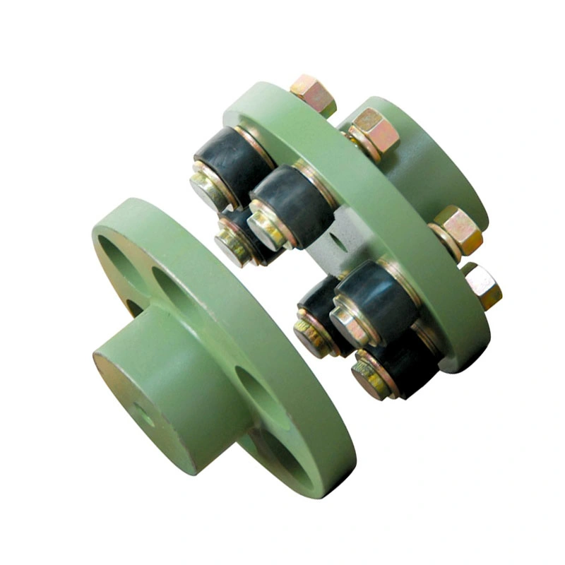
How does a flexible coupling protect connected equipment from shock loads and vibrations?
Flexible couplings play a crucial role in protecting connected equipment from shock loads and vibrations by providing damping and isolation capabilities. When machines or mechanical systems experience sudden shock loads or vibrations, the flexible coupling acts as a buffer, absorbing and dissipating the impact, thereby reducing the transmitted forces and protecting the equipment. Here’s how flexible couplings achieve this:
- Damping of Vibrations: Flexible couplings are often made from materials that exhibit damping properties. When vibrations are transmitted through the shafts, the flexible coupling’s material can absorb a portion of the vibrational energy, converting it into heat. This dissipation of energy helps reduce the amplitude of the vibrations and prevents them from propagating further into the connected equipment.
- Vibration Isolation: In addition to damping vibrations, flexible couplings also offer a degree of vibration isolation. They are designed to decouple the two shafts, which means that vibrations occurring on one shaft are not directly transmitted to the other shaft. This isolation effect prevents vibrations from propagating across the entire system and minimizes the impact on sensitive equipment or nearby components.
- Shock Absorption: When the connected machinery experiences sudden shock loads, such as during a startup or abrupt changes in load, the flexible coupling can act as a shock absorber. The coupling’s design allows it to deform slightly under the impact, absorbing and distributing the shock energy. This prevents the shock from being directly transferred to the connected equipment, reducing the risk of damage or premature wear.
- Misalignment Compensation: Flexible couplings are capable of compensating for misalignment between the shafts. Misalignment can lead to additional stresses and vibrations in the system. By allowing for some degree of angular, parallel, and axial misalignment, the flexible coupling reduces the forces transmitted to the connected equipment and the supporting structures.
- Reduction of Resonance Effects: Resonance is a phenomenon that occurs when the natural frequency of a system matches the frequency of external vibrations, leading to amplified vibrations. Flexible couplings can help avoid resonance effects by altering the system’s natural frequency and providing some level of flexibility that damps the resonance response.
By incorporating a flexible coupling into the drivetrain or power transmission system, equipment manufacturers and operators can significantly improve the reliability and longevity of connected machinery. The coupling’s ability to dampen vibrations, isolate shocks, and compensate for misalignment contributes to a smoother and more stable operation, reducing maintenance requirements and enhancing overall system performance.
In summary, flexible couplings act as protective elements, shielding connected equipment from shock loads and vibrations. Their ability to dampen vibrations, isolate shocks, and compensate for misalignment contributes to a smoother and more reliable operation of various mechanical systems.


editor by CX 2023-10-12